


Yeah, CFav, I thought about that. The last time, though, I had a warn wench* she ended up drinking all my liquor and stealing my ashtrays.
No cooler, but you know it has those ice chests in the side pockets? One side for beer, the other for fish.
*If you don't get it, just look it up on the Internet.
Newest Trak Mate Version 5.1
Moderator: Jani Soderhall
-
Chris Favero
- CHIxILL Master CFav

- Posts: 504
- Joined: Mon Jun 21, 2004 8:48 pm
- Location: chicago
- Contact:
personally WT<i think you should throw a winch on the front of the UAV for the timing cable.you could also mount a PA in the truck.heck,just park it between the start ramps and you have the whole announcers booth,power source timing center in the cab-with tunes!you got a cooler in that thing too?cfav
Freak Bros. Racing
www.chixillskateboards.com
www.chixillskateboards.com
-
Marcos Soulsby-Monroy
- Posts: 233
- Joined: Sun Mar 02, 2003 1:00 am
- Location: League City

-
Pat Chewning
- Pat C.

- Posts: 1400
- Joined: Mon Sep 16, 2002 2:00 am
- Location: Portland Oregon
Winding the cable with 1/2 of the work
Wind the cable from the center. You will only turn the crank 1/2 as much. Maybe even less, because you only have to unwind as much as you need, since both ends are available without unwinding the whole reel.
-- Pat
-- Pat
-
Wesley Tucker
- 1961-2013 (RIP)
")
- Posts: 3279
- Joined: Tue Aug 27, 2002 2:00 am
To continue with the on-going saga,
We ran my new TrakMate at the Southeastern Slalom Series Race . . . er, session, whatever, in Winston Salem on Sunday. Set up was a snap and taking it down was even easier!
There were six of us during the day and I would estimate each skater took at least 10 runs with the clock. Ran without a hitch. No glitches, stammers, lock ups or non-stops. Every run went like, well, clockwork.
I learned one thing yesterday, though, that's kind of a cool tidbit. This isn't necessarily TrakMate related, but certainly applicable to my system. It was HOT yesterday in North Carolina. When I got in my truck to leave at 4:00 the thermostat read 98 degrees. Before that, though, I had the unenviable task of winding up 700 feet of cable. Doing that in the blazing sun AFTER skating for five hours is no fun.
After cranking on that wheel for about five minutes and about dying from exposure, I had a brainstorm: why am I doing this? I have a big truck with lots of room. So I just gathered up all the Cat-5 cable and tossed in the truck with the reel. This morning after a long night's sleep and feeling better, I went to the truck, grabbed a huge wad of cable and brought it inside. In the air conditioning and with a glass of iced tea, I easily wound up the cable in about ten minutes. No sweat . . . literally.
I know on a race weekend this might be a bad idea to do on a Saturday if you have to race again on Sunday. Then again, taking care of the system while back in the motel room sure sounds better than wilting away in the heat when it's not necessary. I know the guys who use phone cord are a little protective and try to get it straight and wound up as soon as they are finished, but the heavier Cat-5 is easy to gather up and untagle later. Of course, the fact that it's heavier is one of the reason winding it in while on the hill is so debilitating.
I know that not everyone has a covered pick up truck bed they can just use as a huge trunk, but it works for me. I'm sure the next time I set up the system on a blistering summer day I will not spend any time cranking and winding that cable. It sure makes everything easier to just do it later when the conditions are a little more ameneable to manual labor.

-
Wesley Tucker
- 1961-2013 (RIP)
- Posts: 3279
- Joined: Tue Aug 27, 2002 2:00 am
It's operational!
After getting my box from Dan, it's taken me a little while to get in gear and finish the timing system. Today I finally got every component wired and completed all troubleshooting and whadda ya' know? It works!
A couple of points to anyone else who decides to assemble their own:
1. The DB-9 work great, but there are TWO KINDS:
a. The kind you must solder
b. Solderless.
Try and find the solderless. The ports are $1.58 each at RadioShack and I used three males and one female. There is one male for the start, the male for the finish and then I created an "extension cord" with a male and female at each end. The solderless ports use pins that you crimp onto the wire and then insert the pinned wire into the port. That is much easier than trying to microsolder the wires to the individual pins. It's cleaner, simpler and much easier to troubleshoot. You can easily see if the wire isn't connected.
Secondly, I used Bill Tway's idea for using electrical plugs and sockets to connect the individual tape switches to the cables. I found out after quite a bit of cussing and bitching that a small tab connects the two left side connections and the two right side connections. After calling Bill to confirm my suspiscions, I found out you have to remove those little tabs. I don't know what they accomplish with an electrical installation, but with a TrakMate it makes sure the circuit is ALWAYS CLOSED. We don't want that. We want the circuit closed to start the timer and then open again then it closes to stop the timer. As you can imagine, with those little tabs, the circuit stays closed all the time and either the timer won't start or it runs continuously. Just something learned through trial and error.
Anyway, I've tested and tested in every combination and the two lanes are working perfectly in both modes. I'm stoked.
-
jeff bonny
- Posts: 46
- Joined: Sat Sep 10, 2005 6:59 am
- Location: vancouver, bc
Re: trakmate, new features
I can vouch for the ease of use of the infrared beams...I'm very glad I chose them over tapeswitches. I would also recommend this as a mounting solution for them: http://thepod.ca/
-
Daniel Groulx
- Posts: 1
- Joined: Tue May 23, 2006 7:19 pm
trakmate, new features
Hello everybody.
My name is Dan from Trakmate.
I see there has been discussion about the new Trakmate Timer.
PC connection
With the new design has a com port so it’s now possible to send data to a PC. I’ll be writing the code to do that this week. The format will be
L1:23.123
R1:25.456
I will not get involved on the PC side of things.
IR Beam Boxes
The new timer is also compatible with the TrakMate infrared beam boxes. These beams are very easy to align and have over 20’ range. There are not the reflective type, it uses a transmit and receive pair. The receiver requires no batteries and is wired to the timer box. The transmit box runs on 4 AA batteries and has no wires connecting to the box.
Instructions
The wiring instructions scroll by on power on. This way you can’t lose the manual.
If you have any questions feel free to ask?
Any features you would like to see?
-
Jani Soderhall
- Former ISSA President (2011-2024)
")
- Posts: 4820
- Joined: Thu Aug 22, 2002 2:00 am
- Location: Sweden, lives in France
- Contact:
I can volonteer one of my engineers if Carl doesn't take on the job. I'll let Daniel know too. I've been asking for this so long and he has told me too that he has done the hardware already, it's just the software which is missing. As it's inside the box, I didn't imagine he wanted anybody else to take it on, but if he wants to, I'm sure Carl or my engineer can work it out. We've put our own timer on hold as TrakMate looked like it was going to do the job. I only need a PC connected timer.jeff bonny wrote:He will do the hardware to make it happen but he has no interest in writing the software.
/Jani
-
Wesley Tucker
- 1961-2013 (RIP)
- Posts: 3279
- Joined: Tue Aug 27, 2002 2:00 am
-
jeff bonny
- Posts: 46
- Joined: Sat Sep 10, 2005 6:59 am
- Location: vancouver, bc
Just talked to Trak Mate and there is no PC interface. He will do the hardware to make it happen but he has no interest in writing the software. We did talk about porting out to an external LED display though and we'll probably talk some more about it. Is this something anyone would be interested in?
-
jeff bonny
- Posts: 46
- Joined: Sat Sep 10, 2005 6:59 am
- Location: vancouver, bc
I just got a system a few days ago and I don't recall him saying anything about it talking to a PC...but then I know I didn't ask either. I'm curious now though and since it's a local call I'm going to ask him tomorrow.Jani Soderhall wrote:I have asked, silence has been the reply.Marcus Seyffarth wrote:Perhaps Dan could tell us if we ask him?
Last time he said he had added the components but hadn't done the programming yet, but that was way before WT got his so I thought that by now it had been done. Maybe not.
...I've been waiting so long, it can't be far off now.
/Jani
-
Jani Soderhall
- Former ISSA President (2011-2024)
- Posts: 4820
- Joined: Thu Aug 22, 2002 2:00 am
- Location: Sweden, lives in France
- Contact:
I have asked, silence has been the reply.Marcus Seyffarth wrote:Perhaps Dan could tell us if we ask him?
Last time he said he had added the components but hadn't done the programming yet, but that was way before WT got his so I thought that by now it had been done. Maybe not.
...I've been waiting so long, it can't be far off now.
/Jani
-
Marcus Seyffarth
- Posts: 607
- Joined: Mon Sep 02, 2002 2:00 am
- Location: Stockholm, Sweden
- Contact:
I'm not 100% but pretty sure that there's no output from my trakmate. Since I don't know what port or pins I should listen to it is kind of hard to start serching with the computer. But my dad has a device that uses LEDs to show what pins on a port that are alive, so I hooked that one up to the trakmate and started and stopped the timer and looked for changes or flashes on the LED's but nothing happened so my guess is that it's not supported yet.
On the parallell port there was quite a few LED's that was lit up, but I couldn't see any variations on start/stop.
Perhaps Dan could tell us if we ask him?
On the parallell port there was quite a few LED's that was lit up, but I couldn't see any variations on start/stop.
Perhaps Dan could tell us if we ask him?
-
Marcus Seyffarth
- Posts: 607
- Joined: Mon Sep 02, 2002 2:00 am
- Location: Stockholm, Sweden
- Contact:
-
Jani Soderhall
- Former ISSA President (2011-2024)
- Posts: 4820
- Joined: Thu Aug 22, 2002 2:00 am
- Location: Sweden, lives in France
- Contact:
PC connection available yet?
I've been communicating with Daniel to obtain information whether the PC connection is really ready. Apparently the parts are all there, but did he have the time to finish the software in the timer to send the signal out to that port?
If you don't have any instructions that makes it a bit uncertain. Marcus could you give it a try and see if something is sent out on that port?
I'm hoping the answer is yes, and the timers that you've received could send it's output to a PC. If yes, I'll place my orders immediately.
/Jani
If you don't have any instructions that makes it a bit uncertain. Marcus could you give it a try and see if something is sent out on that port?
I'm hoping the answer is yes, and the timers that you've received could send it's output to a PC. If yes, I'll place my orders immediately.
/Jani
-
Marcus Seyffarth
- Posts: 607
- Joined: Mon Sep 02, 2002 2:00 am
- Location: Stockholm, Sweden
- Contact:
Thanks!
I gave up right away when there wasn't an instruction included, I guess I should have put the batteries in.
Well now I've done that and soldered the connectors as well. I'm only gonna use this for single lane practice so I didn't bother to put four wires in. It works just fine and I hope to take it for a live testrun tomorrow!
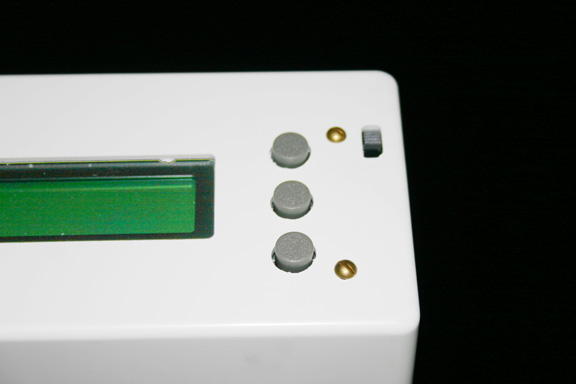
The middle button resets the timer and the upper one changes mode on startup, but what does the lower do?
Also mine says 5.2 is there a difference?
/Marcus
I gave up right away when there wasn't an instruction included, I guess I should have put the batteries in.
Well now I've done that and soldered the connectors as well. I'm only gonna use this for single lane practice so I didn't bother to put four wires in. It works just fine and I hope to take it for a live testrun tomorrow!
The middle button resets the timer and the upper one changes mode on startup, but what does the lower do?
Also mine says 5.2 is there a difference?
/Marcus
-
Wesley Tucker
- 1961-2013 (RIP)
- Posts: 3279
- Joined: Tue Aug 27, 2002 2:00 am
Marcus,
When it's done I'll post a pic or two. In truth, I'm having to develop a new skill I've never had before: micro soldering. Putting the DB-9 connectors to the wire takes solder and I'm far removed from the last time I ever held a hot iron in my hand.
Getting it wired and doing the trouble shooting is taking some time I haven't had in the past couple of weeks. I've also made the solemn pledge not to rush doing this and therefore, going a bit slow. I'd rather take the time to do it right than try and get it done only to have to it twice. I'm doing things like shrink sealing all the open splices on the cabling and getting the connections as clean as possible to insure there's no chance of a cross connectiong and short circuit.
By the way, on start up you'll see a scroll across the board with the wiring instructions:
Start
9 pin connector near edge
Pins 3, 8 Left Lane Tape Switch
Pins 4, 9 Right Lane Tape Switch
Finish 9 pin connector in middle
Pins 3, 8 Left Lane Tape Switch
Pins 4, 9 Right Lane Tape Switch
If you're using the telephone style wire, be sure and match your Red Green to Left Lane Start and Finish and Black Yellow to the Right Lane Start and Finish.
I'm using Cat 5 cable that have brown, blue, orange and green wire, but the matching scheme is the same, just different colors.
Last edited by Wesley Tucker on Tue May 02, 2006 11:13 pm, edited 1 time in total.
-
Marcus Seyffarth
- Posts: 607
- Joined: Mon Sep 02, 2002 2:00 am
- Location: Stockholm, Sweden
- Contact:
-
Wesley Tucker
- 1961-2013 (RIP)
- Posts: 3279
- Joined: Tue Aug 27, 2002 2:00 am
Newest Trak Mate Version 5.1
I got my new Trak Mate:
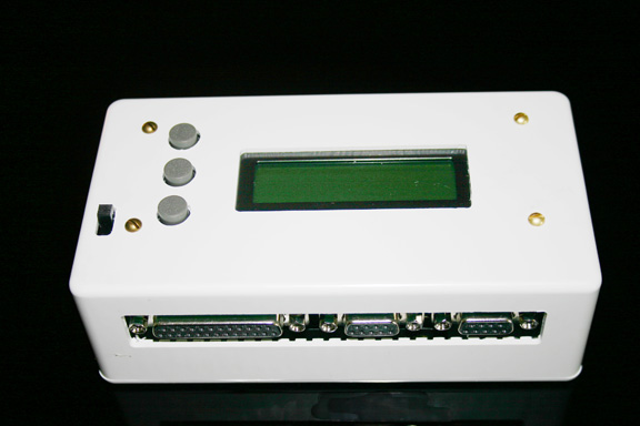
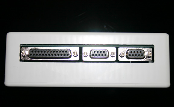
Dan was true to his word and reconfigured it for newer connections. The box now has two DB-9 ports and one DB-25 for sound output:
Also included in the new design is a third button. I'm not sure what it does, but I'm assuming it's an accessory that is available IF someone wants to program in an addetional feature:
One other significant alteration is the switch from a single 9-volt to four 1.5volt "AA" batteries. As I saw Parsons modify his box to take the four "AA"s, I'm assuming this is better power-wise compared to the more expensive transistor battery.